
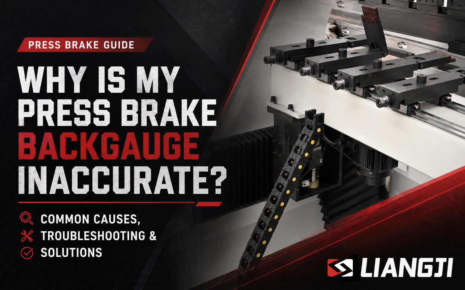
I.Introduction: Backgauge
Backgauge accuracy is one of the most critical factors affecting bending precision on a CNC press brake. Even a positioning error of just a few tenths of a millimeter can lead to inconsistent flange lengths, incorrect bend dimensions, material waste, and costly rework.
When backgauge positioning becomes inconsistent, many operators assume the CNC controller is at fault. In reality, positioning errors are often caused by mechanical wear, insufficient maintenance, improper calibration, or transmission issues.
This guide explains the most common causes of backgauge inaccuracy, practical troubleshooting methods, and how a well-designed backgauge system can significantly improve long-term bending precision.
II. Signs of an Inaccurate Backgauge
Your backgauge may require inspection if you notice any of the following:
- Different flange lengths when producing identical parts
- Dimensions vary even when using the same CNC program
- Poor repeatability during continuous production
- X-axis positioning errors
- Frequent manual adjustments after positioning
- Increasing scrap rates caused by inconsistent dimensions
Identifying these symptoms early can prevent unnecessary downtime and improve production efficiency.
III. Common Causes of Press Brake Backgauge Inaccuracy
1. Ball Screw Wear
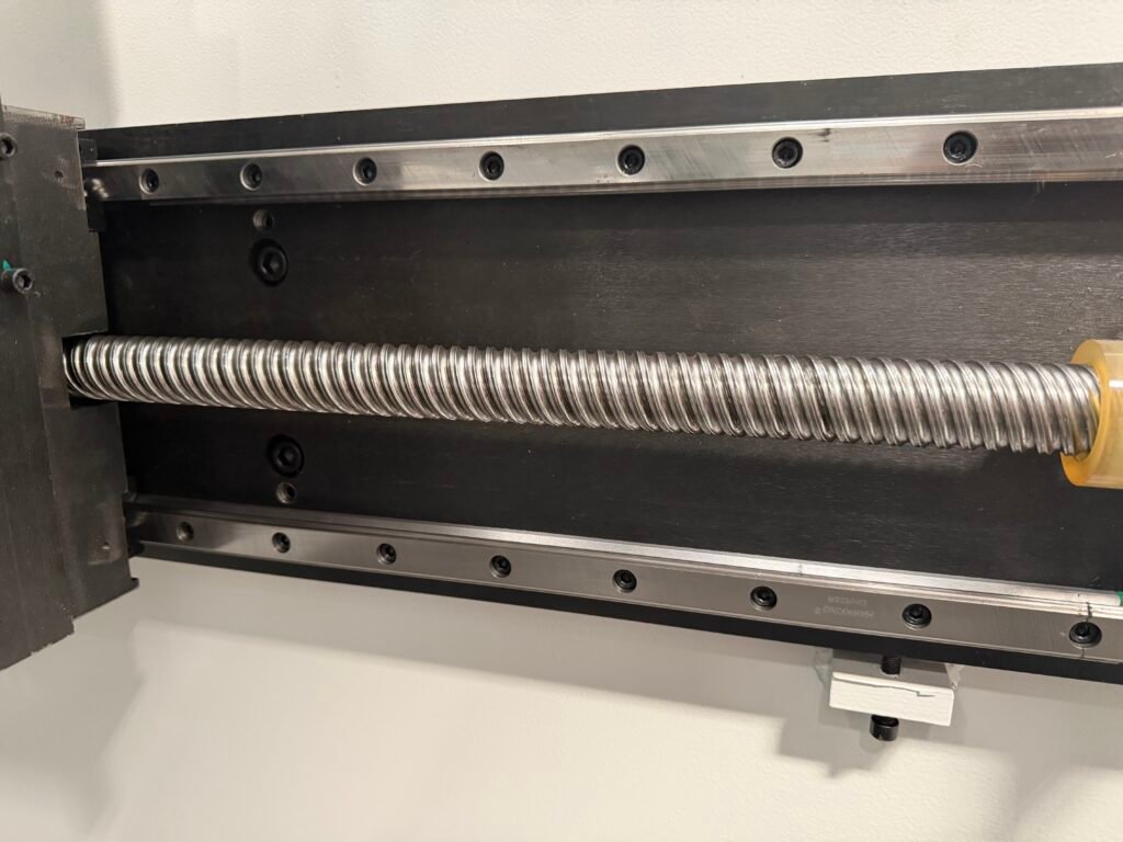
The ball screw converts the servo motor’s rotary motion into precise linear movement. Over time, continuous operation can increase backlash, reducing positioning accuracy and repeatability.
The ball screw is one of the most important transmission components in a CNC press brake backgauge system. It converts the rotary motion of the servo motor into precise linear movement, allowing the backgauge fingers to move accurately to the programmed position.
During long-term operation, the continuous acceleration, deceleration, and repeated positioning cycles can gradually cause wear between the ball screw and nut. As the internal clearance increases, backlash may occur, reducing positioning accuracy and repeatability.
Even a small amount of mechanical clearance can affect bending dimensions, especially when producing precision components that require consistent flange lengths.
Common Causes
Long-Term Continuous Operation
High-frequency production cycles place repeated loads on the ball screw. Over thousands of positioning movements, gradual wear may increase the clearance between the screw and nut.
Insufficient Lubrication
Proper lubrication reduces friction between the ball bearings and raceway surfaces. When lubrication is insufficient, wear accelerates and the service life of the ball screw is reduced.
Contamination from Dust and Metal Chips
In a sheet metal processing environment, dust and metal particles can enter the transmission system if protection is insufficient. These contaminants may damage the precision surfaces of the ball screw.
Symptoms
- Position varies slightly between repeated cycles
- Reduced backgauge repeatability
- Increasing positioning deviation
- Mechanical backlash during movement
- Abnormal noise from the transmission system
Solution
- Measure ball screw backlash using appropriate inspection tools.
- Check lubrication condition and remove contaminants.
- Adjust preload if the design allows adjustment.
- Replace the ball screw and nut assembly when wear exceeds acceptable limits.
- Perform positioning calibration after maintenance.
A high-quality ball screw with proper maintenance can significantly improve the long-term accuracy and reliability of a CNC press brake backgauge system.
2.Linear Guide Rail Wear or Contamination
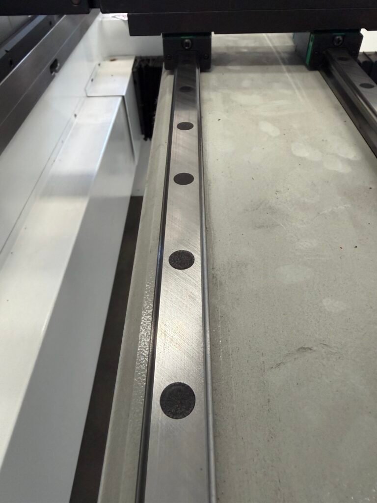
Linear guide rails provide stable and precise movement for the backgauge beam. They support the moving components while maintaining accurate alignment during high-speed positioning.
Because CNC press brake backgauges frequently perform rapid forward and backward movements, the guide rail system must maintain smooth motion with minimal friction. Wear, contamination, or insufficient lubrication can increase resistance and cause unstable movement.
Common Causes
Accumulation of Dust and Metal Chips
During sheet metal processing, small metal particles and dust can enter the working area. If they accumulate on the guide rails, they may damage the contact surfaces and reduce movement smoothness.
Insufficient Lubrication
Without proper lubrication, friction between the guide rail and slider increases. This not only affects positioning accuracy but also accelerates wear of the guide components.
Long-Term Mechanical Wear
After extended operation, the rolling elements inside the guide blocks may experience wear, resulting in increased clearance and reduced rigidity.
Symptoms
- Jerky or uneven movement of the backgauge
- Increased resistance during positioning
- Abnormal vibration during rapid movement
- Positioning errors during repeated operations
- Increased noise from the guide system
Solution
- Clean guide rails regularly to remove dust and metal particles.
- Apply recommended lubricant according to maintenance intervals.
- Check guide block condition and movement smoothness.
- Replace worn guide blocks if excessive clearance occurs.
- Ensure the guide system remains properly aligned.
A well-maintained linear guide system helps the backgauge move smoothly and ensures stable positioning accuracy throughout the machine’s service life.
3. Servo Motor or Drive Problems
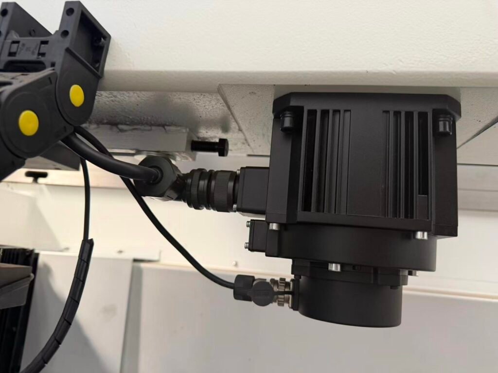
Servo motors are responsible for driving the backgauge axis with high-speed and high-precision movement. Together with servo drives and feedback systems, they form a closed-loop positioning system that allows the CNC controller to achieve accurate axis control.
When servo parameters are incorrect, electrical components fail, or feedback signals become unstable, the backgauge may not reach the commanded position accurately.
Unlike purely mechanical problems, servo-related issues may appear intermittently and can be more difficult to diagnose.
Common Causes
Incorrect Servo Parameter Settings
Servo drives require optimized parameters for acceleration, speed, torque response, and positioning control. Incorrect settings may cause unstable movement or reduced accuracy.
This can happen after:
- Servo drive replacement
- CNC system upgrade
- Parameter modification
Encoder Feedback Problems
The encoder is usually integrated inside the servo motor and provides real-time feedback of motor position and speed.
If encoder signals become unstable or incorrect, the servo drive cannot accurately determine the actual position, resulting in positioning errors.
Electrical Connection Problems
Loose connectors, damaged cables, or poor signal transmission between the servo motor, drive, and CNC controller may cause intermittent positioning failures.
Symptoms
- Random positioning errors
- Servo alarms displayed on the CNC controller
- Unstable axis movement
- Abnormal acceleration or deceleration
- Backgauge fails to return accurately to the reference position
Solution
- Check servo alarm history and diagnostic information.
- Verify encoder feedback signals.
- Inspect motor cables and electrical connections.
- Recalibrate servo parameters when necessary.
- Replace damaged servo motors, drives, or feedback components.
A properly configured servo system ensures fast response, accurate positioning, and reliable operation of the CNC press brake backgauge.
4. Encoder Calibration Errors
The encoder is typically integrated inside the servo motor and plays a critical role in the backgauge positioning system. It continuously detects the servo motor’s rotation angle and speed, then sends real-time feedback signals to the servo drive and CNC controller.
Based on this feedback, the control system calculates the actual backgauge position and automatically corrects any positioning deviation to maintain high accuracy.
If the servo motor encoder loses calibration, provides unstable feedback signals, or becomes damaged, the backgauge may experience positioning errors, inaccurate return-to-zero positioning, or reduced repeatability.
Symptoms
- Position deviation occurs repeatedly
- Home position shifts unexpectedly
- Servo alarms appear
- Backgauge repeatability decreases
Possible Causes
- Encoder calibration drift
- Damaged encoder or feedback cable
- Poor connection between encoder and servo drive
- Incorrect servo parameters
Solution
- Check encoder feedback signals
- Inspect encoder cables and connectors
- Recalibrate servo parameters
- Replace damaged servo motor or encoder components if necessary
5. Incorrect CNC Parameters
The CNC controller uses various parameters to calculate the movement distance, speed, acceleration, and positioning accuracy of the backgauge system. If these parameters are modified incorrectly after software updates, maintenance, or system replacement, the backgauge may lose its original positioning accuracy.
Even when the mechanical components are working properly, incorrect CNC settings can cause the actual position to differ from the programmed value.
Common Causes
Incorrect X-axis Offset
The X-axis offset defines the relationship between the programmed position and the actual mechanical position. If this value is incorrect, the backgauge may consistently stop before or beyond the required position.
For example, if the offset value changes by 1 mm, every workpiece produced may have a dimensional error of approximately 1 mm.
Incorrect Machine Reference Point
The reference point (machine zero position) is the foundation for all axis movements. If the machine zero position is incorrectly set, all subsequent positioning calculations may become inaccurate.
This issue often occurs after:
- CNC system replacement
- Encoder maintenance
- Servo motor replacement
- Parameter restoration
Improper Acceleration and Deceleration Settings
Acceleration and deceleration parameters directly affect how smoothly the backgauge moves.
If acceleration is set too high:
- Mechanical vibration may occur
- Positioning stability may decrease
- Transmission components experience greater impact loads
If acceleration is too low:
- Positioning time increases
- Production efficiency decreases
Solution
- Compare current parameters with the original factory backup.
- Check axis offsets and reference positions.
- Verify acceleration and speed settings.
- Perform axis calibration after parameter adjustment.
- Always save a backup of CNC parameters before making any modifications.
Proper CNC parameter management ensures that the control system and mechanical structure work together to maintain accurate positioning.
6. Mechanical Looseness
Mechanical rigidity is essential for maintaining backgauge accuracy. Even a small amount of looseness in the transmission system can create positioning errors because the CNC controller may command the correct movement, but the mechanical components cannot accurately transfer that movement.
Over time, continuous operation, vibration, and repeated acceleration and deceleration can gradually loosen mechanical connections.
Common Causes
Loose Motor Couplings
The coupling connects the servo motor shaft with the ball screw. If the coupling becomes loose, the motor may rotate normally while the ball screw movement is delayed, creating positioning deviation.
Symptoms:
- Backgauge position changes between cycles
- Abnormal mechanical noise
- Increased backlash
Worn Bearings
Bearings support the rotating components of the transmission system. Wear or damage can create additional clearance, affecting movement stability and repeatability.
Symptoms:
- Unstable movement
- Increased vibration
- Reduced positioning accuracy
Loose Fasteners
Loose bolts or mounting screws can cause slight movement between components, especially during rapid axis movement.
Regular inspection of:
- Motor mounting bolts
- Guide rail fixing screws
- Backgauge frame connections
helps prevent accuracy loss.
Timing Belt Wear (If Equipped)
Some backgauge systems use timing belts for power transmission. Belt aging, stretching, or insufficient tension can introduce positioning errors.
Solution
- Check all mechanical connections regularly.
- Tighten loose fasteners according to recommended torque values.
- Inspect couplings and bearings for wear.
- Replace damaged transmission components.
- Verify positioning accuracy after mechanical adjustment.
A rigid and properly maintained transmission system is the foundation of long-term backgauge precision.
7. Insufficient Lubrication
Proper lubrication is essential for the smooth operation and long-term accuracy of a CNC press brake backgauge system.
Linear guides, ball screws, and other moving components rely on lubrication to reduce friction and prevent premature wear. When lubrication is insufficient, increased resistance can affect positioning accuracy and accelerate mechanical damage.
Common Causes
Insufficient Lubricant
When lubrication levels are too low, friction between moving surfaces increases. This can cause uneven movement and reduce positioning repeatability.
Contaminated Lubricant
Metal chips, dust, and other contaminants can mix with grease or oil, damaging precision components and reducing service life.
Incorrect Lubrication Frequency
Over-lubrication or under-lubrication can both create problems.
- Too little lubrication causes wear.
- Excessive lubrication may attract dust and contaminants.
Following the manufacturer’s recommended maintenance schedule is essential.
Symptoms
- Increased movement resistance
- Abnormal operating noise
- Uneven backgauge movement
- Reduced positioning accuracy
- Accelerated wear of guide rails and ball screws
Solution
- Clean guide rails and transmission components regularly.
- Apply suitable lubricant according to manufacturer recommendations.
- Inspect lubrication points during routine maintenance.
- Replace contaminated grease when necessary.
Regular lubrication maintenance is one of the simplest and most cost-effective ways to maintain backgauge accuracy and extend machine service life.Physical Location: Located at the rear of the machine, behind the tooling area.
III. How to Diagnose Backgauge Positioning Errors
A systematic inspection can quickly identify the root cause.
| Inspection Item | What to Check |
|---|---|
| Ball Screw | Backlash and wear |
| Linear Guides | Smooth movement and contamination |
| Servo Motor | Alarm history and encoder feedback |
| Encoder | Calibration accuracy |
| CNC Parameters | Axis offsets and reference position |
| Mechanical Components | Couplings, bearings and bolts |
| Lubrication | Grease condition and maintenance intervals |
Following this sequence helps reduce unnecessary downtime and avoids replacing components that are still functioning properly.
IV. Example of a High-Precision Backgauge System
While regular maintenance is essential, the mechanical design of the backgauge system has an equally significant impact on long-term positioning accuracy.
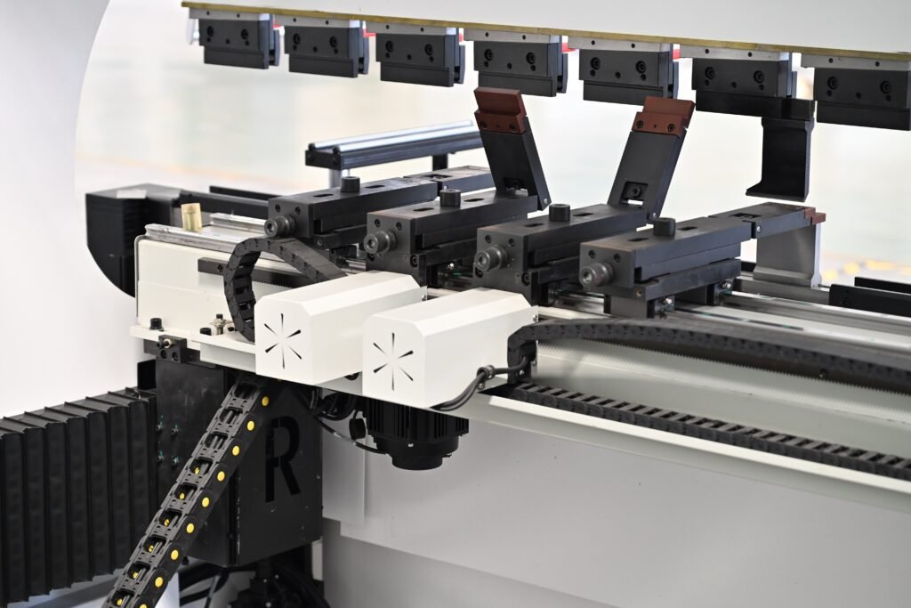
The LIANGJI Performance Electro-Hydraulic CNC Press Brake features a Center-Drive™ Precision Backgauge System, specifically engineered to minimize positioning errors while maintaining high-speed operation.
Unlike conventional side-driven designs, LIANGJI uses a centrally positioned ball screw combined with dual HIWIN or TBI linear guide rails. This balanced transmission structure reduces torsional deflection across the beam, ensuring smoother movement and more consistent positioning accuracy during continuous production.
V. Why the LIANGJI Center-Drive™ Precision Backgauge Stands Out
Center-Driven Ball Screw Design
The centrally mounted ball screw distributes driving force evenly across the entire beam, reducing twisting during rapid positioning and improving repeatability.
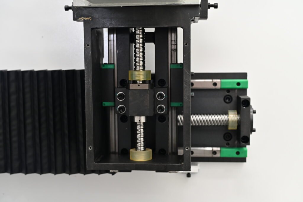
Dual HIWIN/TBI Linear Guides
High-quality dual linear guide rails provide excellent rigidity and smooth movement while minimizing wear over long production cycles.
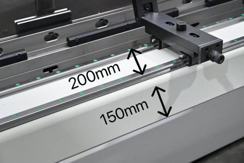
Heavy-Duty Beam Construction
A 10 mm thick, 200 mm wide heavy-duty beam significantly reduces deformation during high-speed movement, helping maintain positioning stability even under demanding production conditions.
High-Speed Positioning
- X-axis speed: up to 400 mm/s
- R-axis speed: up to 200 mm/s
- Mechanical positioning accuracy: ±0.02 mm
Fast positioning shortens production cycles without sacrificing precision.
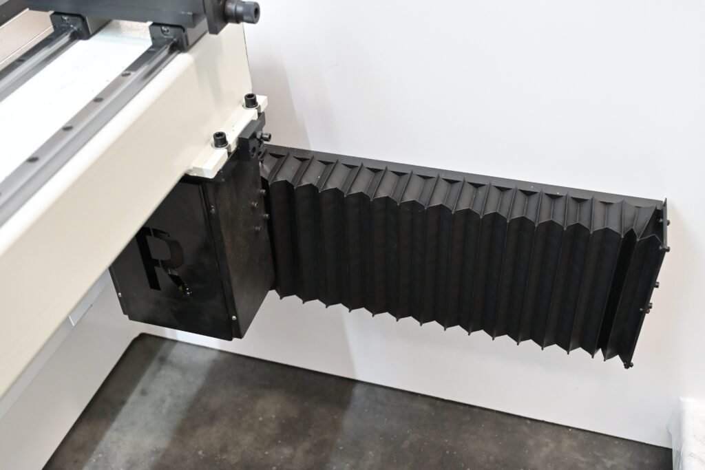
Fully Enclosed R-Axis Protection
Customized accordion covers protect precision transmission components from dust, metal chips and coolant contamination, extending service life and reducing maintenance requirements.
Flexible Multi-Axis Configuration
The programmable X, R, Z1 and Z2 axes allow accurate positioning for complex sheet metal parts while improving production efficiency.
Hardened Backgauge Fingers
Medium-frequency quenched backgauge fingers with HRC 55–60 hardness provide excellent wear resistance and maintain positioning accuracy over extended periods of industrial use.

Preventive Maintenance Tips
To maintain consistent positioning accuracy:
- Clean guide rails daily.
- Lubricate moving components regularly.
- Inspect ball screw backlash periodically.
- Verify axis calibration every few months.
- Check encoder cables during routine maintenance.
- Back up CNC parameters before modifications.
Preventive maintenance not only improves bending accuracy but also extends the service life of the entire backgauge system.
VI. Conclusion
Backgauge positioning errors are rarely caused by a single component. In most cases, mechanical wear, poor maintenance, calibration issues, or transmission design all contribute to reduced accuracy.
Routine inspection and preventive maintenance help restore positioning precision, reduce scrap, and improve production efficiency.
For manufacturers seeking long-term reliability, the LIANGJI Performance Electro-Hydraulic CNC Press Brake combines a rigid machine frame, closed-loop electro-hydraulic control, and the Center-Drive™ Precision Backgauge System to deliver stable, repeatable positioning for demanding sheet metal fabrication applications.